T41-EP [Part 2] Display and front panel boards
Intro#
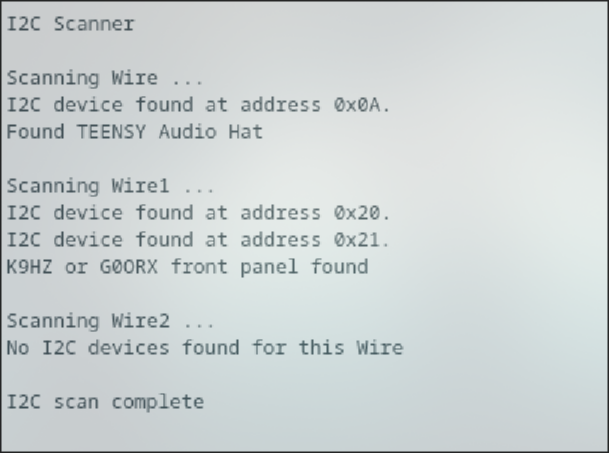
In T41-EP [Part 1] Software Defined Transceiver I completed the main board of the T41-EP transceiver and run initial tests to verify the voltages. I also confirmed the I²C bus detects the Audio Hat and tested the on/off smart switch based on the ATtiny85.
In this post, I am going to connect and test the display, build and test the front panel board, and load the T41-EP Phoenix firmware for first time.
Let’s get started!
The Display#
The T41-EP project supports 5, 7 and 9-inch 800x900 pixel displays driven by the RA8875 controller. The main board can supply either 3 V or 5 V, configurable on both the main board and in the display board. Communication between the two is handled over a 4-wire SPI interface.
I opted for this 7-inch display, configured with a 4-wire SPI connection, 5.0 V power supply, and a capacitive touch screen. Details of the selected displayed are in the table below.
| Item | Selection |
|---|---|
| Pin Header Connection | 4-Wire SPI |
| Power Supply | 5.0 V |
| Touch Pannel | 7" capacitive touch panel with controller |
| MicroSD Car Interface | Pin Header Connection |
| Front Chip | ER3304-1 |
Voltage Selection
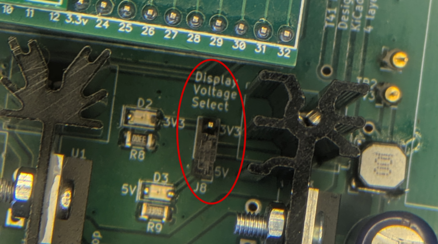
The display is pre-configured for 5.0 V, although it can be configured for 3.3 V by bridging J8.
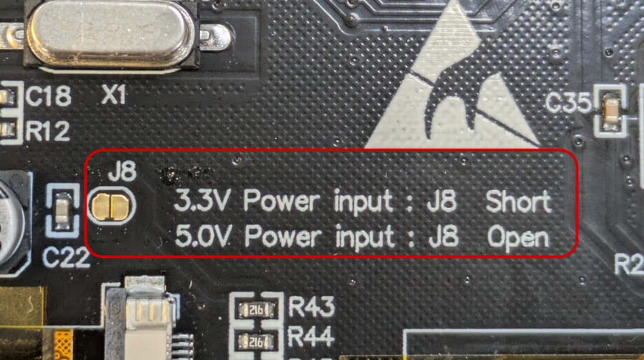
I also need to ensure the main board is configured to supply 5.0 V to the display. This is done by placing a jumper on the J8 connector.
Fixing the display connector
The display connector on the main board is a 5x2 header. The easiest way to connect the display is by using an IDC 5x2 ribbon cable. However, to fit the display’s connector, two unncessary pins must be removed.
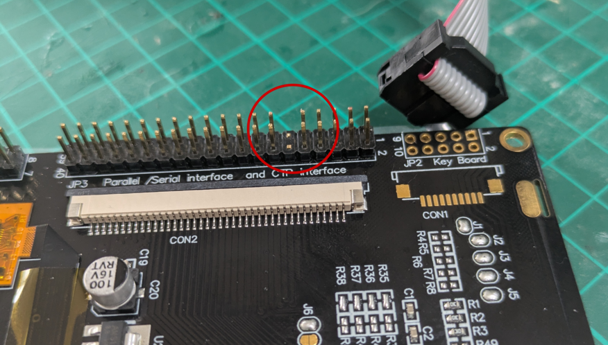
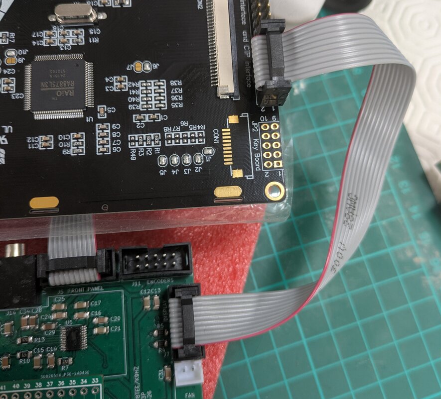
Once the pins are removed, I can use an IDC ribbon cable to connect the display to the main board.
Front Panel and encoder boards#
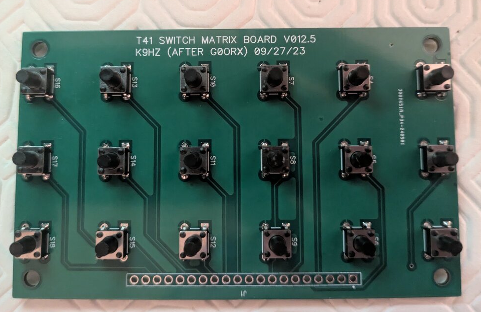
The front planel consist of a control board, a switch matrix board with 18 push buttons, and four encoder boards, each with a rotary encoder. The matrix and encoder boards connect to the front panel board, which presents itself to the main board as a single I²C device.
Since I am already testing the main board and running an I²C scan, this seemed a good time to build these boards.
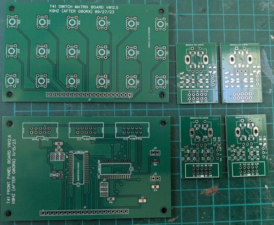
Front Panel and Switch Matrix Board
I followed the Front Panel Assembly Manual.
The front panel board uses two MCP23017 programmable I/O expanders to interface with all 18 switches, the push button of each of the four encoders, and the two directional outputs of each encoder. Additional pins are available to control two LEDs, which can be connected to the front panel control board.
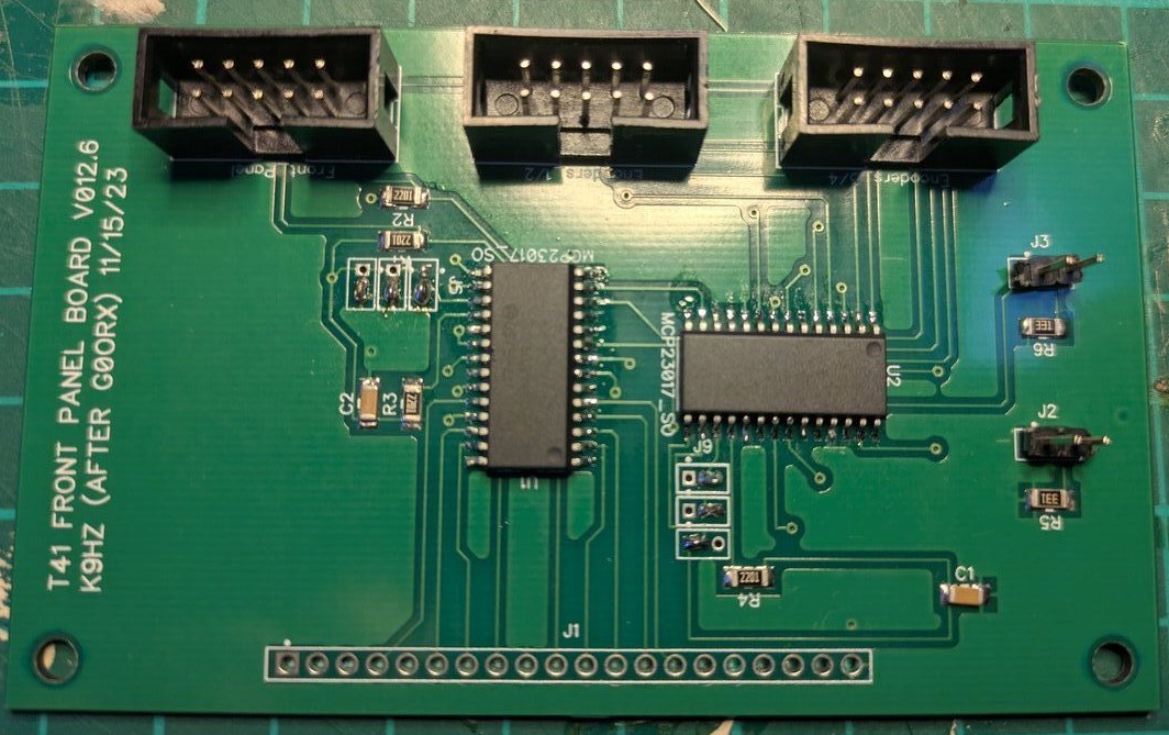
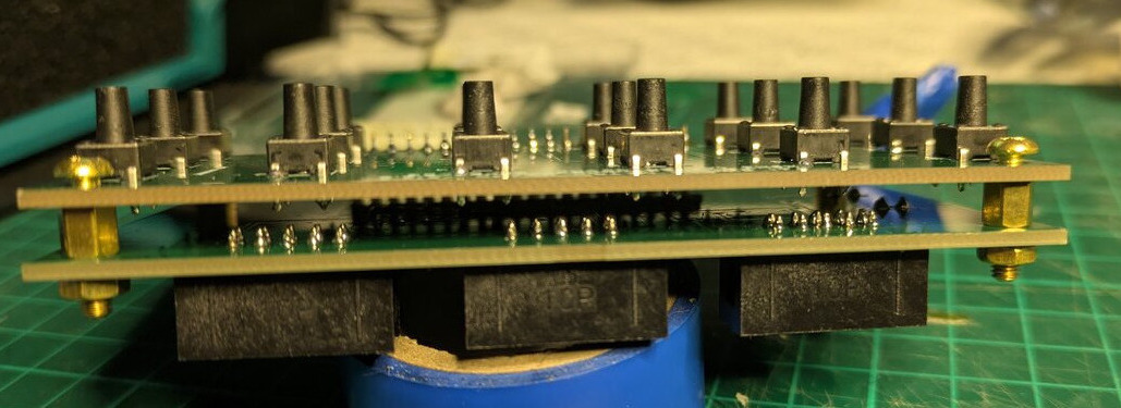
The front panel control board and the switch matrix board are the same and are designed to be stacked using 3M spacers.
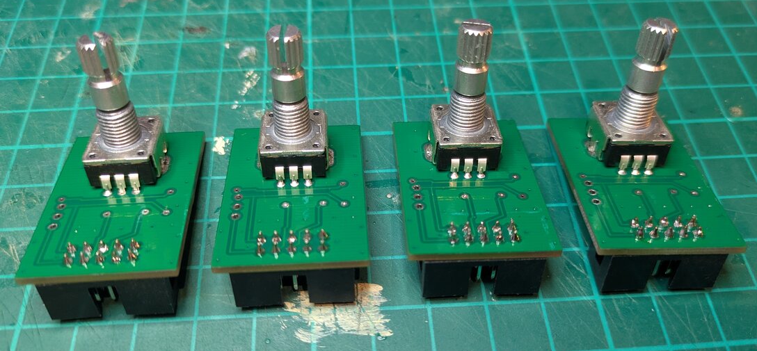
Encoder boards
The T41-EP uses four encoder functions: frequency tuning, fine tune, filter adjustment and volume. The dual encoder boards can be daisy-chained using a single ribbon cable with 2 IDC connectors, since the control board only provides two IDC headers for the four encoder boards.
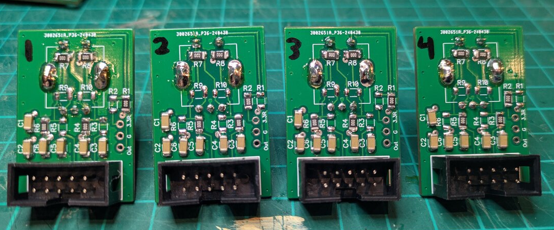
I followed the Double Encoder Board Assembly manual closely, except for the placement 0 Ω resistors, which I determined using this diagram. This is critical, as it defines the GPIO mapping for each enconder’s push button and ensures that the quadrature outputs are uniquerly assigned when multiple enconders share the same connector.
| # | Type | R1 | R2 | R3 | R4 | R5 | R6 | R7 | R8 | R9 | R10 |
|---|---|---|---|---|---|---|---|---|---|---|---|
| 1 | Volume | x | x | x | x | x | |||||
| 2 | Fine Tune | x | x | x | x | x | |||||
| 3 | Tune | x | x | x | x | x | |||||
| 4 | Filter | x | x | x | x | x |
Testing#
The front panel manual refers to the frontpanel_test Arduino sketch, which can be used to test the fron panel board. We can load this sketch onto the Teensy and monitor the serial output while pressing buttons on the switch matrix board and rotating the encoders in both directions. We should also be able to test the two LEDs connected to the front panel board; these should turn on and off as we press any buttons.
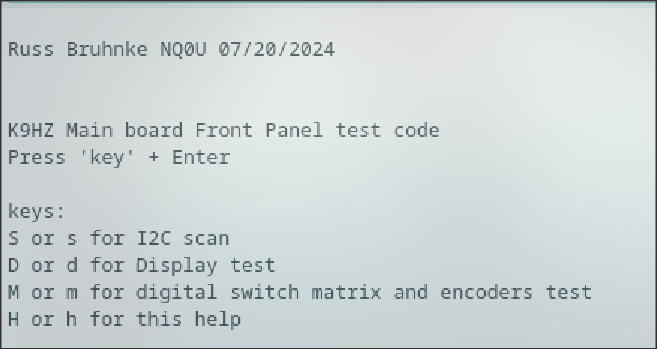
Additionally, the Phoenix repository includes a TestMainAndFrontPanel utility, which provides a small interactive test suite that can:
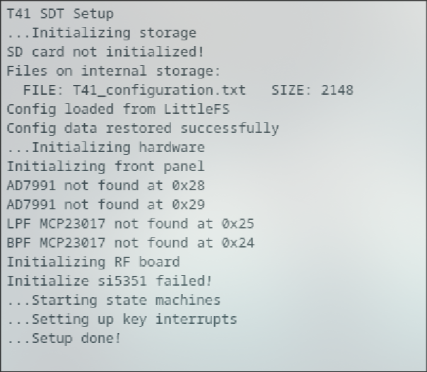
- Perform an I²C scan
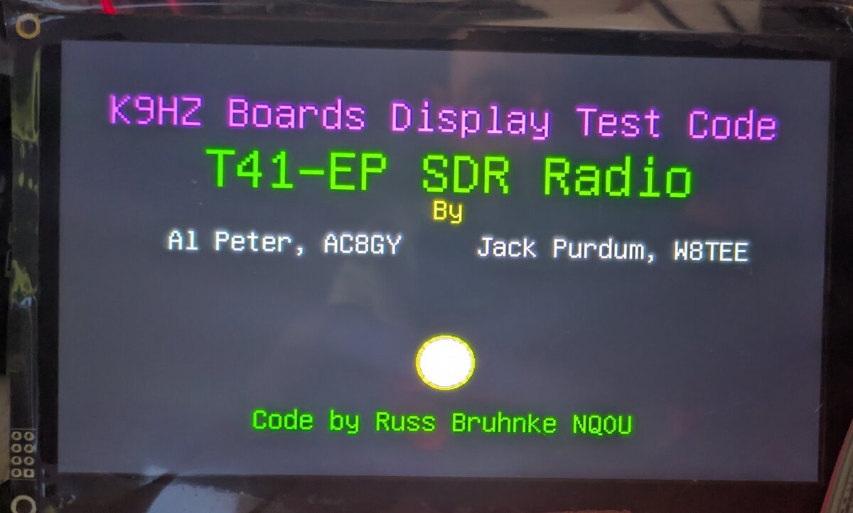
- Test the display
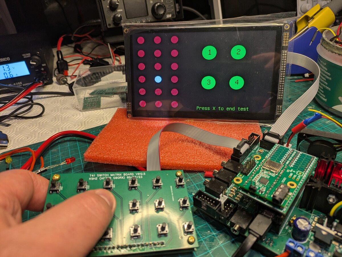
- Test the front panel board, including all 18 switches in the switch matrix board and the four rotary encoders
Serial Monitor
Display Test Complete...

Testing Matrix...
Press X and Enter to end test
Encoder Switch 2 Pushed
Encoder1 = 1
Encoder1 = 1
Encoder1 = -1
Encoder1 = -1
Encoder2 = 1
Encoder2 = 2
Encoder2 = -1
Encoder2 = -2
Encoder4 = -1
Encoder4 = -3
Encoder4 = -2
Encoder4 = -2
Encoder3 = 1
Encoder3 = 3
Encoder3 = -1
Encoder3 = -1
Encoder Switch 2 Pushed
Encoder Switch Released
Encoder Switch 1 Pushed
Encoder Switch Released
Encoder Switch 0 Pushed
Encoder Switch Released
Software#
Finally, I download compile, and upload the Phoenix firmware to the Teensy. The entry point for the project is the PhoenixSketch.
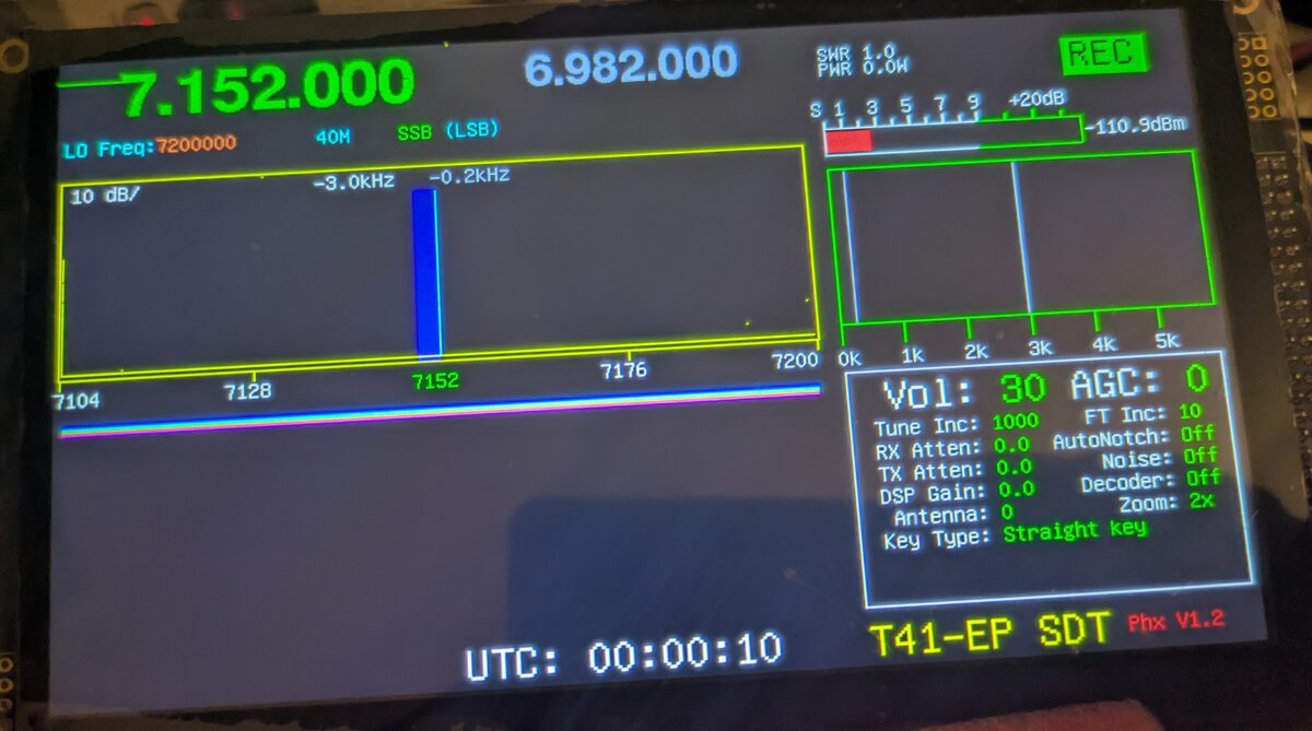
With this, I complete the main board and most of the input/output controls—buttons, encoders and display—which will allow me to test the next boards as I complete them and start working with the Phoenix firmware.