KeithSDR Transceiver [Part 3]: Main board, power and encoders
This is the third part in the build process for the KeithSDR transceiver. Following on from parts 1 and 2 [placeholder link to part 1] and [placeholder link to part 2], this stage focuses on integrating the core components onto the main printed circuit board (PCB). We’ll be installing sockets for the Teensy and Audio hat, mounting the display with spacers, and setting up the I2C encoders and power supply.
Previuos posts:
- KeithSDR Transceiver [Part 1]: Building the software
- KeithSDR Transceiver [Part 2]: Testing the display
Teensy and Audio Hat#
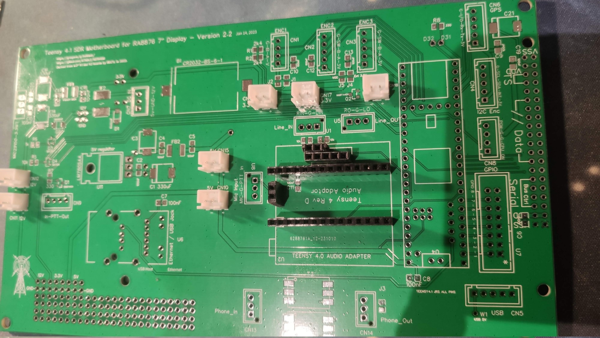
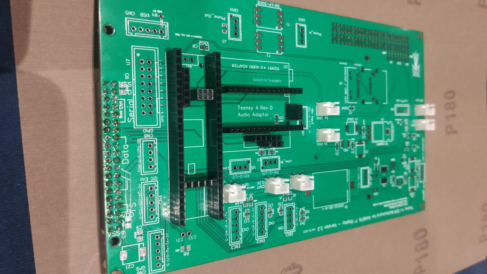
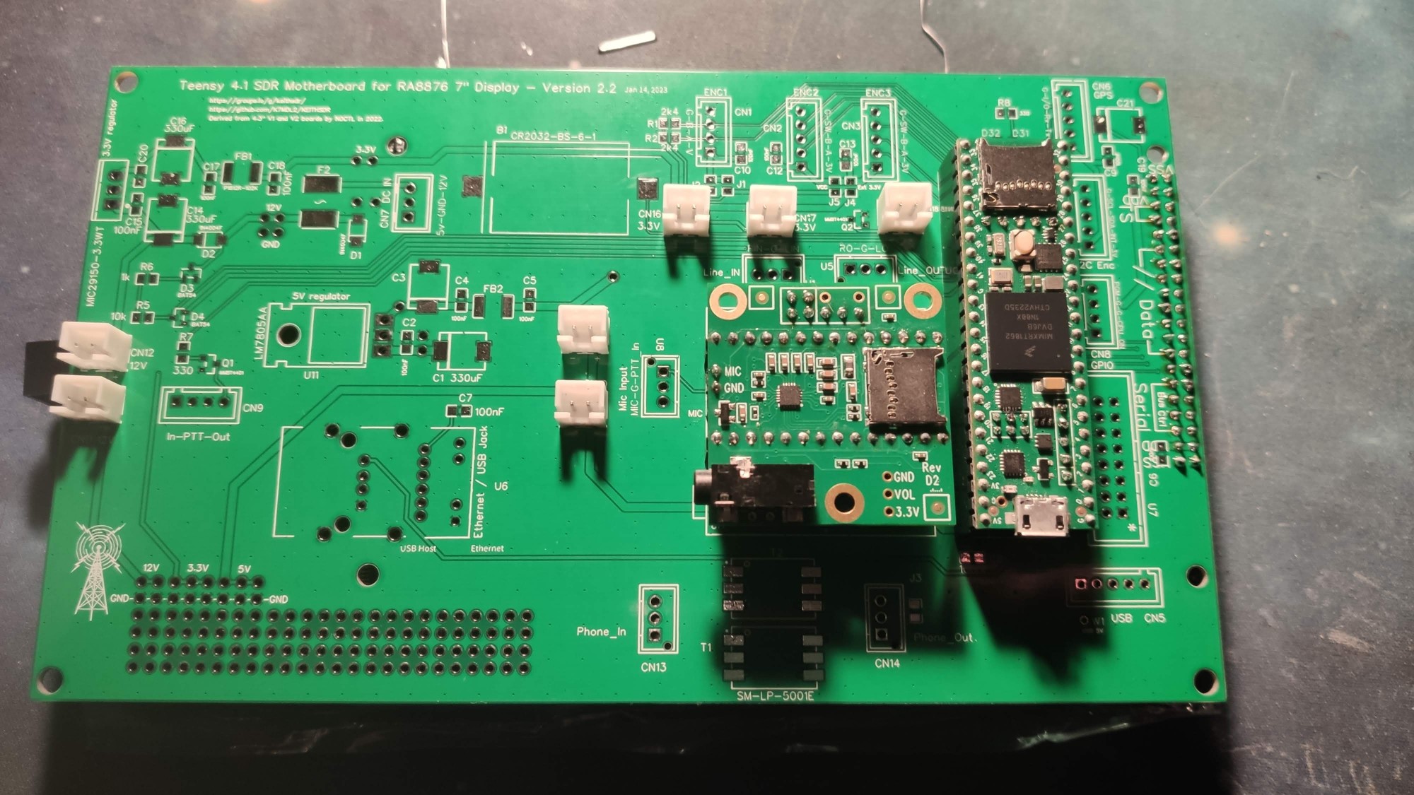
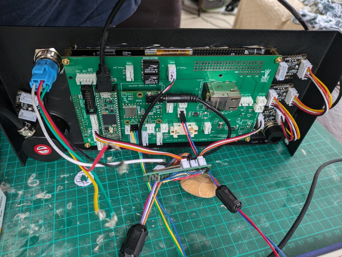
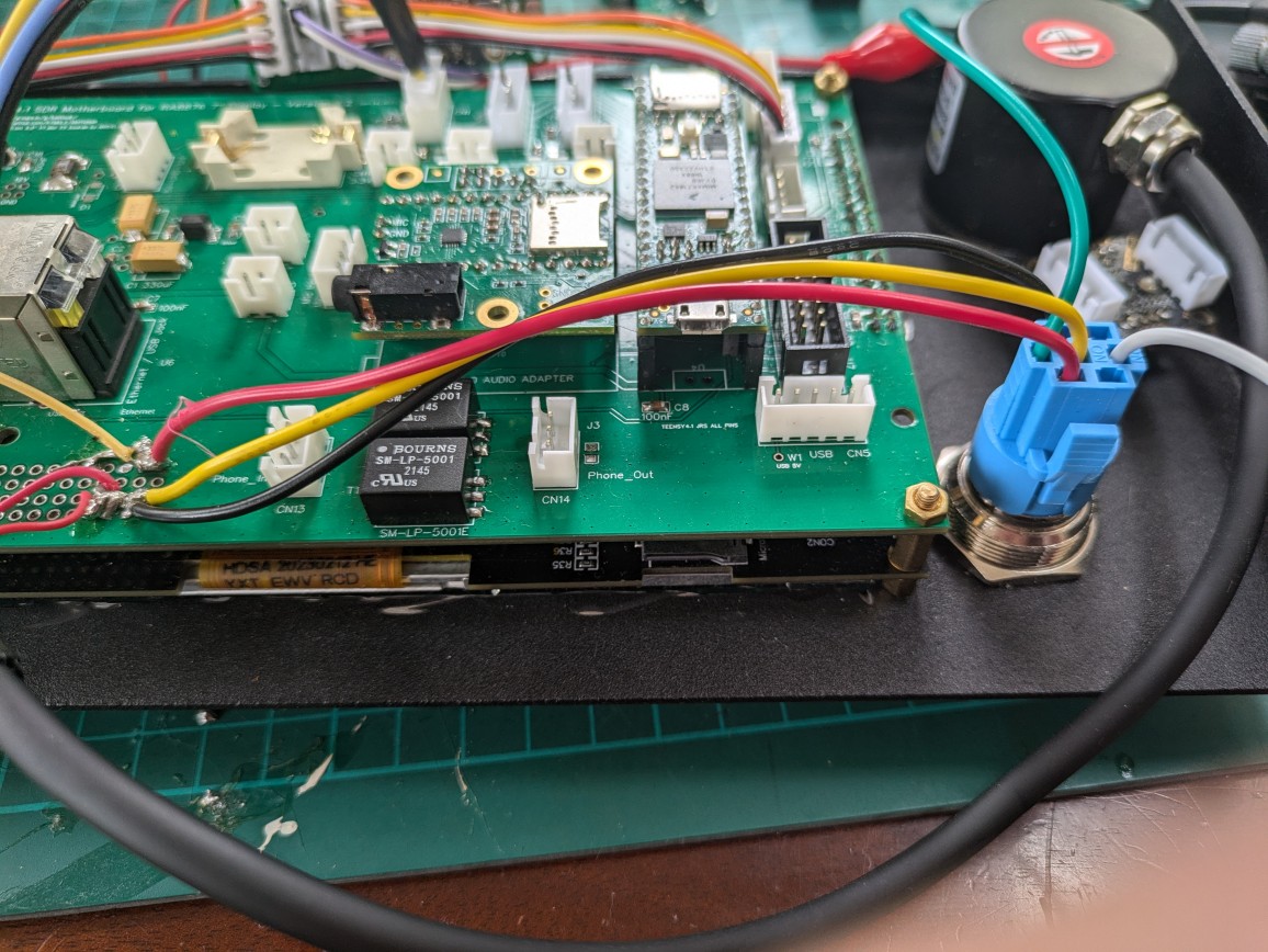
The main PCB including the Teensy, most of the sockets, ethernet port,
audio transformers and wired the power button.
Attaching the display to the main board using spacers
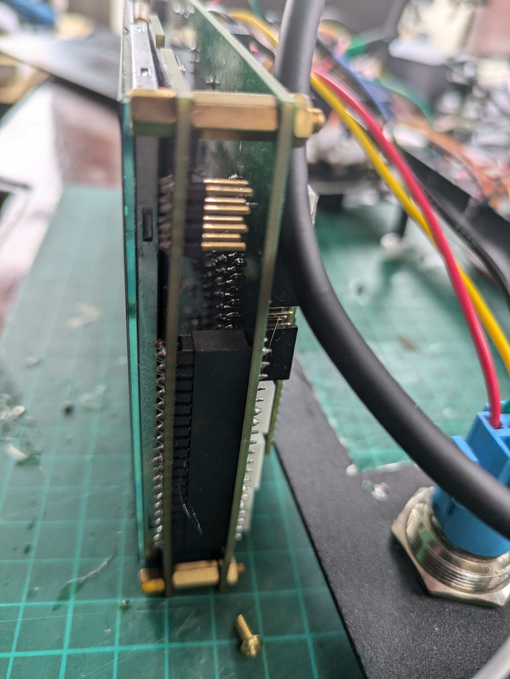
The main PCB board, display, encoders and power button mounted in the front part of the case.
Optical Encoder#
The optical encoder I’m using is rated to operate with a supply voltage between 5V and 20V. The ENC1 socket can be configured via the J2 jumper to output either 3.3V or 5V; however, in my case, it didn’t function correctly with either setting. It seems this particular encoder requires a voltage above 5V to operate reliably. As a workaround, I connected the encoder’s A and B signal lines to the ENC1 socket as usual, but supplied power directly from a 12V source to the encoder’s positive terminal.
I2C Encoders and I2C Terminator#
The main board includes a single I2C socket. While it’s possible to daisy-chain multiple I2C devices, I2C communication is quite sensitive to long wiring. To ensure stable operation, it’s recommended to use an I2C terminator.
In this setup, the receiver includes the following I2C devices:
- Touchscreen (internally connected to the Teensy)
- Audio Hat (also internally connected to the Teensy)
- 4× I2C Encoders (Duppa I2C Encoder v2.1)
- QRP Labs Si5351A Synthesizer
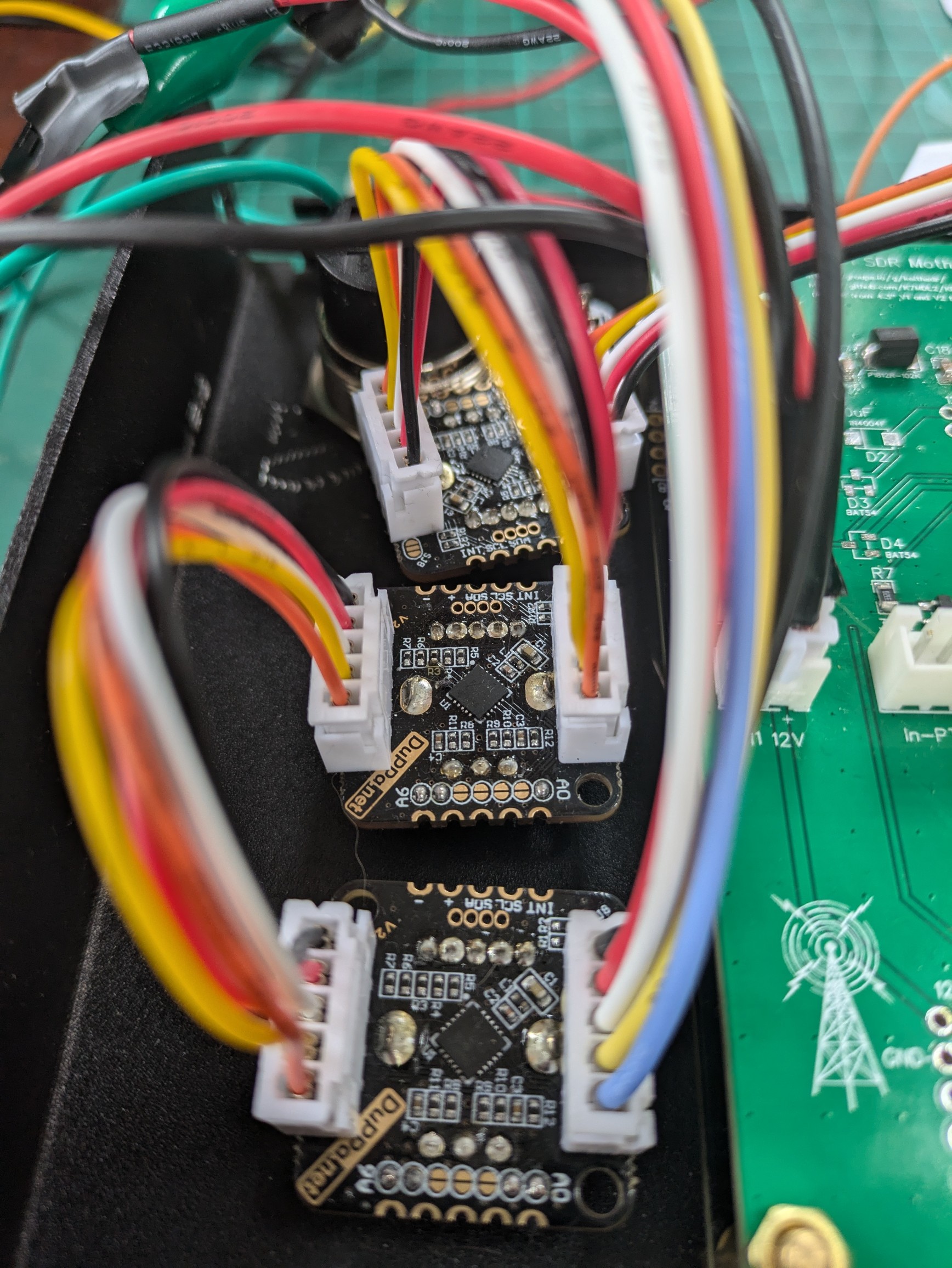
To improve I2C reliability, I’m using an LTC4311 I2C bus repeater/terminator, mounted on a small PCB with three sockets. One socket connects to the CN4 header on the main board. From another socket, I daisy-chain the four Duppa I2C encoders. The remaining socket is used to connect the QRP Labs synthesizer.
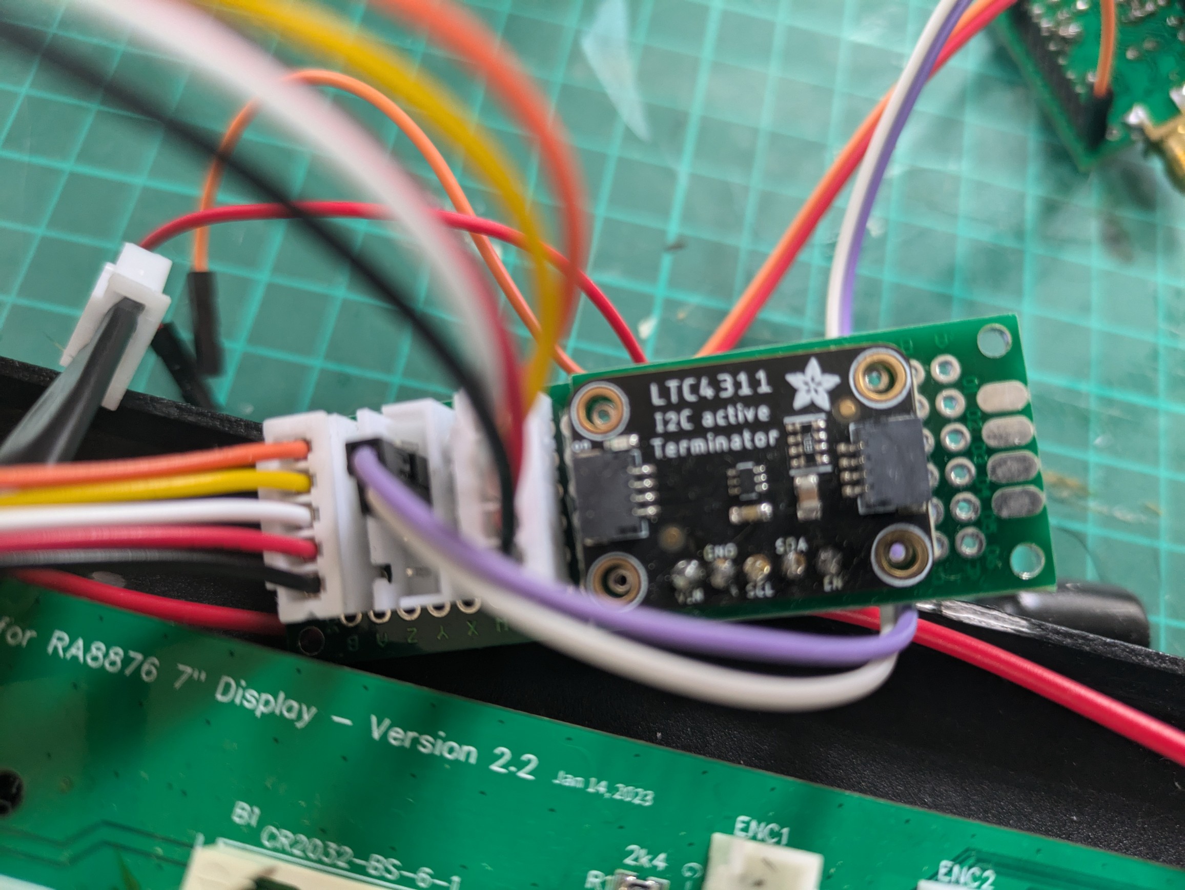
Note: I chose not to chain all the I2C devices directly together because the pinout of the I2C port on the main PCB doesn’t match the pin configuration on the small PCBs of the Duppa encoders. To make them compatible, some rewiring underneath the PCB was required to ensure proper connections. To keep things clean and reliable, I opted to connect them through the I2C terminator board instead.
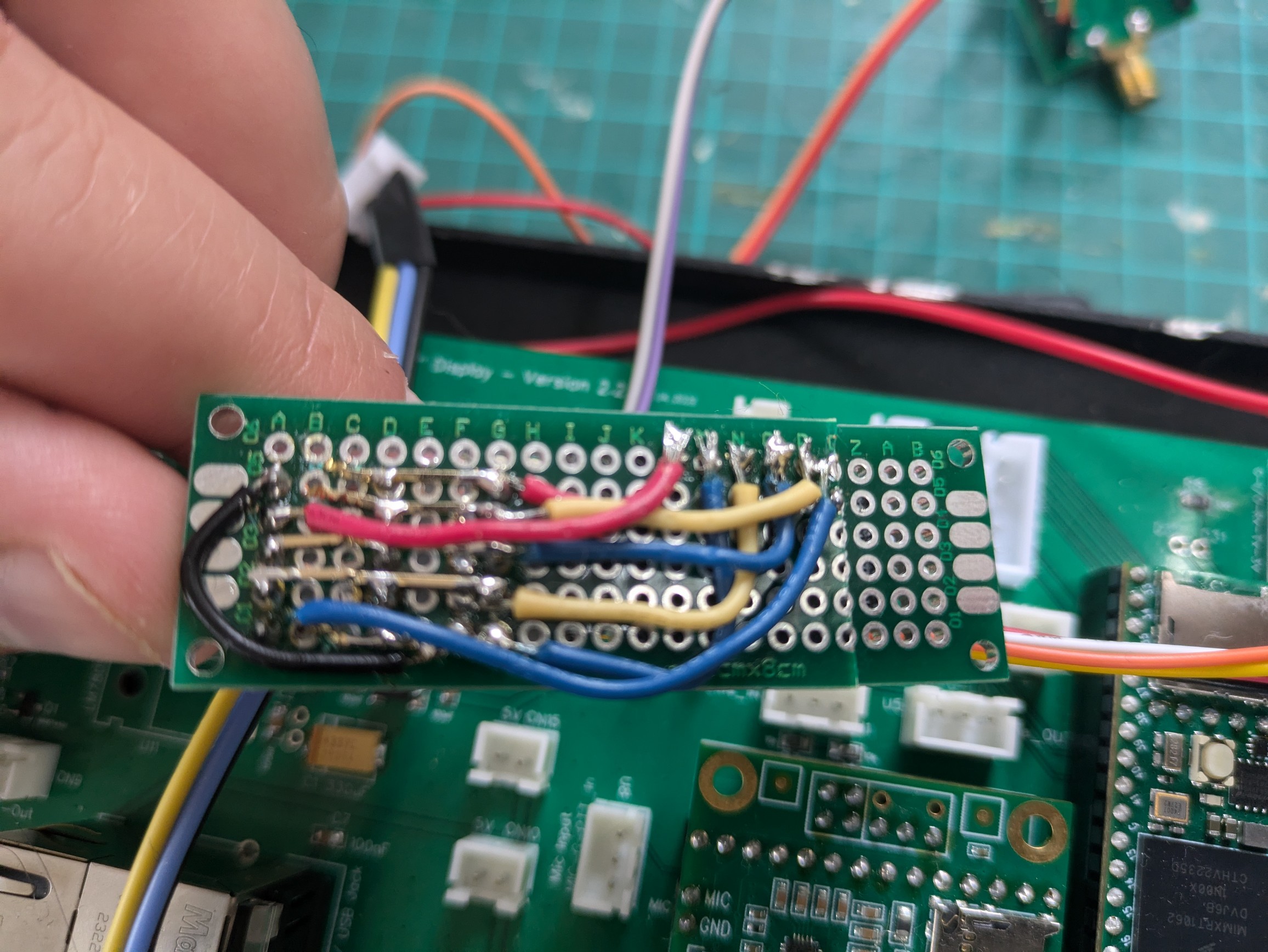
Below, you can see three of the Duppa encoders chained together. Each encoder’s PCB includes a set of seven jumpers that allow you to configure the I2C address and ensure no conflicts between devices. For more details, check out the official product page:
The I2C address configuration for each encoder can be found in the RadioConfig.h file of the KEITHSDR project. Here’s an example:
  #ifdef I2C_ENCODERS
  #if I2C_ENC1_ENABLE > 0
    #define I2C_ENC1_ADDR       (0x61)  	/* Address 0x61 only - Jumpers A0, A5 and A6 are soldered.*/
  #endif
  #if I2C_ENC2_ENABLE > 0
    #define I2C_ENC2_ADDR       (0x62)  	/* Address 0x62 only - Jumpers A1, A5 and A6 are soldered.*/
  #endif
  #if I2C_ENC3_ENABLE > 0
    #define I2C_ENC3_ADDR       (0x63)  	/* Address 0x63 only - Jumpers A0, A1, A5 and A6 are soldered.*/
  #endif
  #if I2C_ENC4_ENABLE > 0
    #define I2C_ENC4_ADDR       (0x64)  	/* Address 0x64 only - Jumpers A2, A5 and A6 are soldered.*/
  #endif
  #if I2C_ENC5_ENABLE > 0
    #define I2C_ENC5_ADDR       (0x65)  	/* Address 0x65 only - Jumpers A0, A2, A5 and A6 are soldered.*/
  #endif
  #if I2C_ENC6_ENABLE > 0
    #define I2C_ENC6_ADDR       (0x66)  	/* Address 0x66 only - Jumpers A1, A2, A5 and A6 are soldered.*/
  #endif
#endif // I2C_ENCODERS
Upon powering up the radio, you should see the connected I2C devices detected in the serial terminal output.
Running I2C Scanner ****
Scanning...
I2C device found at address 0x0A  (SGTL5000)
I2C device found at address 0x38  (RA8875,FT6206)
I2C device found at address 0x60  (MPL3115,MCP4725,MCP4728,TEA5767,Si5351)
I2C device found at address 0x61  (MCP4725,AtlasEzoDO,DuPPaEncoder)
I2C device found at address 0x62  (LidarLite,MCP4725,AtlasEzoORP,DuPPaEncoder)
I2C device found at address 0x63  (MCP4725,AtlasEzoPH,DuPPaEncoder)
I2C device found at address 0x64  (AtlasEzoEC,DuPPaEncoder)
done
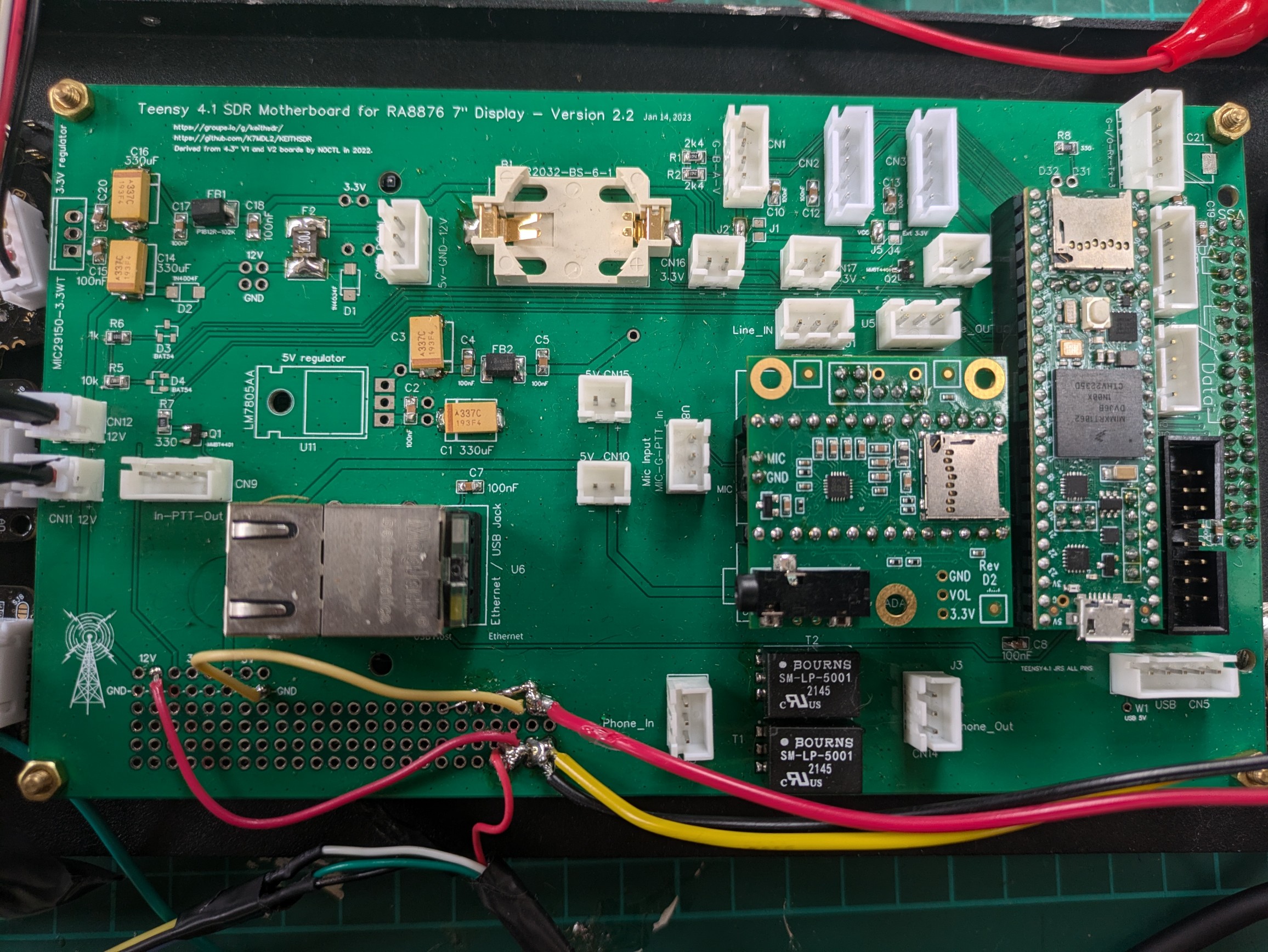
Power Supply#
The radio is powered using a 12V supply, with different components operating at 5V and 3.3V levels. The Teensy microcontroller used in this project is powered with 5V, although it technically supports input voltages ranging from 3.3V to 5V.
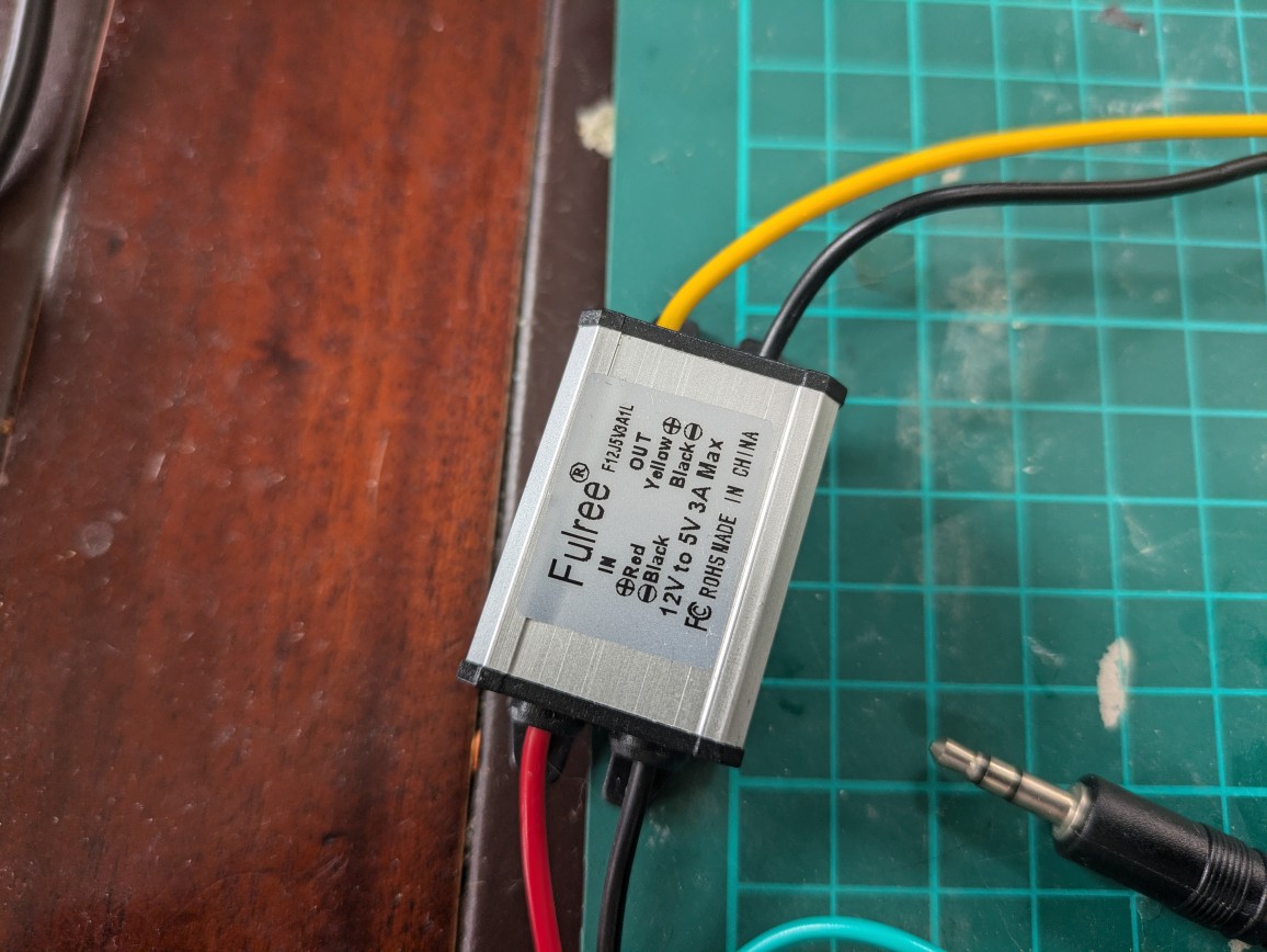
The main PCB provides space for onboard voltage regulators to convert 12V down to 5V and 3.3V. However, in this setup, an external 12V-to-5V converter is used instead, as recommended in other builds. The 3.3V , required for some peripherals, can be generated via a dedicated voltage regulator or taken directly from the Teensy’s 3.3V output.
⚠️ It’s essential to use a clean, low-noise power supply to avoid introducing RFI (Radio Frequency Interference). In my case, I used what I had available, but better results can be achieved with a dedicated low-RFI power source.
12V to 5V voltage regulator
Power button mounted in the front part of the case and wired up to the main PCB
The Teensy supplies 3.3V from its onboard regulator, which can be used to power other 3.3V components such as I2C devices.
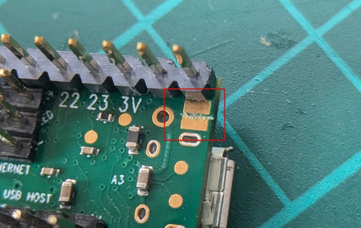
Once the radio is fully powered independently, it’s important to cut the trace on the PCB that previously allowed the Teensy to be powered through the USB port. Doing this prevents power conflicts, ensuring the USB connection is used only for data.
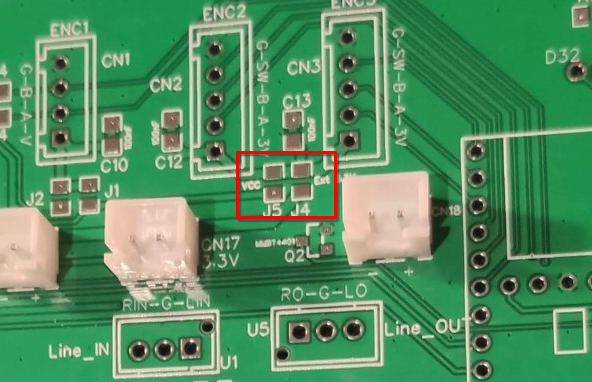
The I2C interface in this project operates at 3.3V. There are two configuration jumpers on the board:
-
The first jumper selects between 3.3V or 5V for the encoders. I also using ENC1 for the optical encoder and since it doesn’t work with either 3.3V or 5V I left this jumper open.
-
The second jumper chooses the source of the 3.3V supply — either from the Teensy or from an external regulator. I’m using the 3.3V provided by the Teensy, so this jumper is also left open.
Wrapping Up#
This setup works well once everything is properly wired and powered. Getting the voltages right and using clean power helps avoid issues, especially with I2C. The Teensy provides 3.3V for low-voltage components, and the encoders can be configured for either 3.3V or 5V, which makes things flexible.
There’s a bit of trial and error involved, especially with wiring and matching pinouts, but once it’s all connected, it works!