KeithSDR Transceiver [Part 2]: Testing the display
In KeithSDR Transceiver [Part 1]: Building the software Building the software][KeithSDR Transceiver [Part 1]: Building the software]] I have installed the Arduino IDE, Teensyduino and I have successfully compiled and upload the software of the KeithSDR receiver.
Next I am trying to test the display.
Testing the display#
:PROPERTIES: nil:END: To test the display I decided to use a breadboard to connect the display SPI interface to the Teensy, following this schematic. Then, I connected the Teensy to the laptop and I inspect the debug messages in the serial monitor to see if the Teensy recognizes the display.
I faced two different problems with this approach:
- The display didn’t turn on, didn’t show any signs of life.
- I could see the following errors in the serial monitor:
Initializing SDR_RA887x Program
FFT Size is 4096

Running I2C Scanner
Scanning...
I2C device found at address 0x38  (RA8875,FT6206)
done

Initializing RA8876 Display
2D ready failed
2D ready failed
2D ready failed
The Teensy was actually recognizing the display, however there was the 2D ready failed error and the display didn’t turn
Fixing the display backlight#
By going through the forum I found out that to turn on the display backlight we need to have the proper jumper configuration in the display. The jumper configuration is documented in the display datasheet.
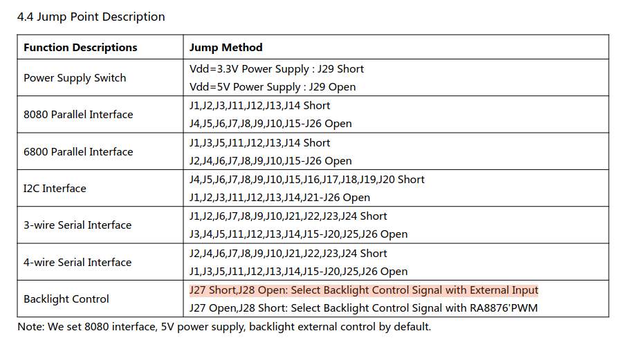
In my display I have the highlighted configuration for J27 and J28:
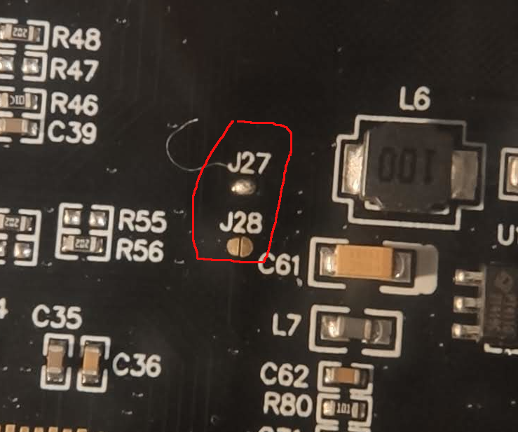
However, we need “J27 Open,J28 Short: Select Backlight Control Signal with RA8876’PWM” so I had to take the iron, remove the short in J27 and create a new one in J28.
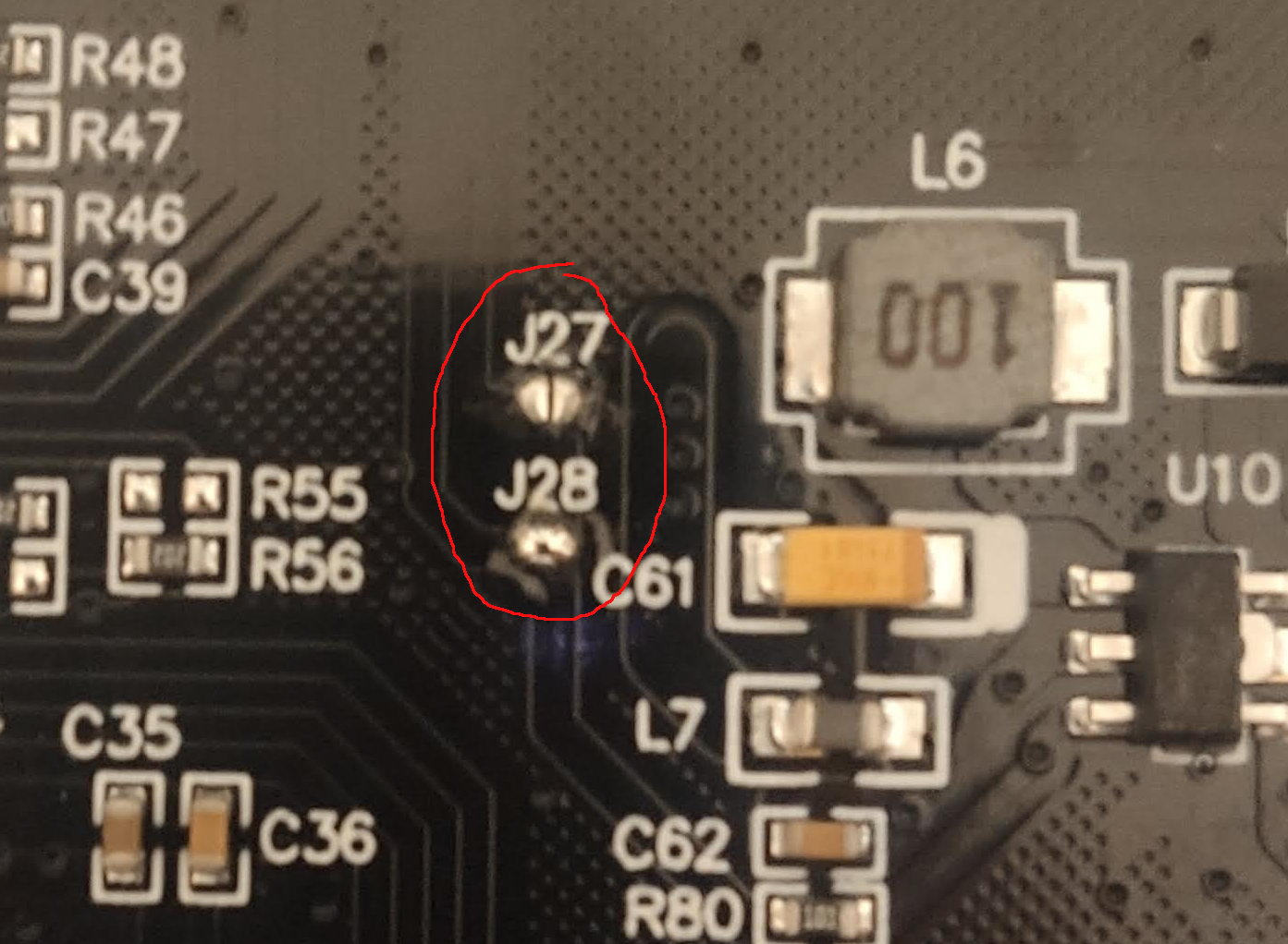
This fix the backlight problem and the display now is turning on.
Fixing ‘2D ready failed’#
2D ready failed is a error thrown by the Ra8876LiteTeensy library.
Ra8876LiteTeensy/src/RA8876_t3.cpp:
void RA8876_t3::check2dBusy(void)
{  ru32 i;
   for(i=0;i<50000;i++)   //Please according to your usage to modify i value.
   {
   delayMicroseconds(1);
    if( (lcdStatusRead()&0x08)==0x00 )
    {return;}
   }
   Serial.println("2D ready failed");
}
Apparently this error can be thrown due to a combination of longer wires connecting the Teensy with the display SPI interface and the speed of the interface itself. I should be able to drop the speed of the interface and get the display working. That can be done by modifying the following lines of code that currently is set to 50 MHz:
/build/KEITHSDR/SDR_RA8875/SDR_RA8875.ino
DPRINTLN(F("Initializing RA8876 Display"));
tft.begin(50000000UL);  // 10 is very slow, 30, much better, 40-50 seem to be were perf gain flattens off.
// Works up to 70Mhz but so little perf gain above 40Mhz thaqt 50Mhz seems a solid compromise.
However, I couldn’t make this work even dropping the frequency down to 10 MHz. The problem could be caused by any bad wire connecting the Teensy and the display.
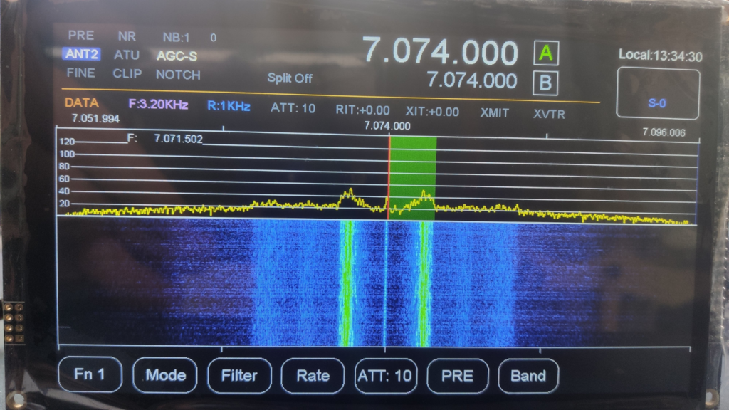
I decided to take another route and test the display directly using the main PCB board, so I went ahead and I solder the sockets for the display, the audio card and the Teensy. I connected the 3 components to the main board and the microUSB cable from the Teensy to the computer. I can see now in the serial monitor the Teensy is initializing properly with no errors and the display is finally working: