KeithSDR Transceiver [Part 4]: The RF Receiver
Previuos posts:
- KeithSDR Transceiver [Part 1]: Building the software
- KeithSDR Transceiver [Part 2]: Testing the display
- KeithSDR Transceiver [Part 3]: Main board, power and encoders
Summary#
In this post, I will focus on the reception side of the SDR radio. Although KEITHSDR support various transceiver modules, many are no longer available. Some alternatives could be adapted, provided they offer I/Q output and can be controlled by the Teensy microcontroller.
For my build, I chose to begin with the QRP Labs receiver module, which is already supported by KEITHSDR and I’ll figure out the transmission part later.
The QRP Labs receiver is an affordable kit that includes a band-pass filter kit (BPF) for one of the HF bands improving signal selectivity by filtering out unwanted frequencies. To enable tuning across the desired frequency range, a stable local oscillator (LO) is required. For this purpose, I’m using the QRP Labs Si5351A Synthesizer module.
The 20m filter#
The QRP Labs receiver comes with a band-pass filter (BPF) kit designed for a specific HF band. For this project, I chose the 20m band-pass filter.
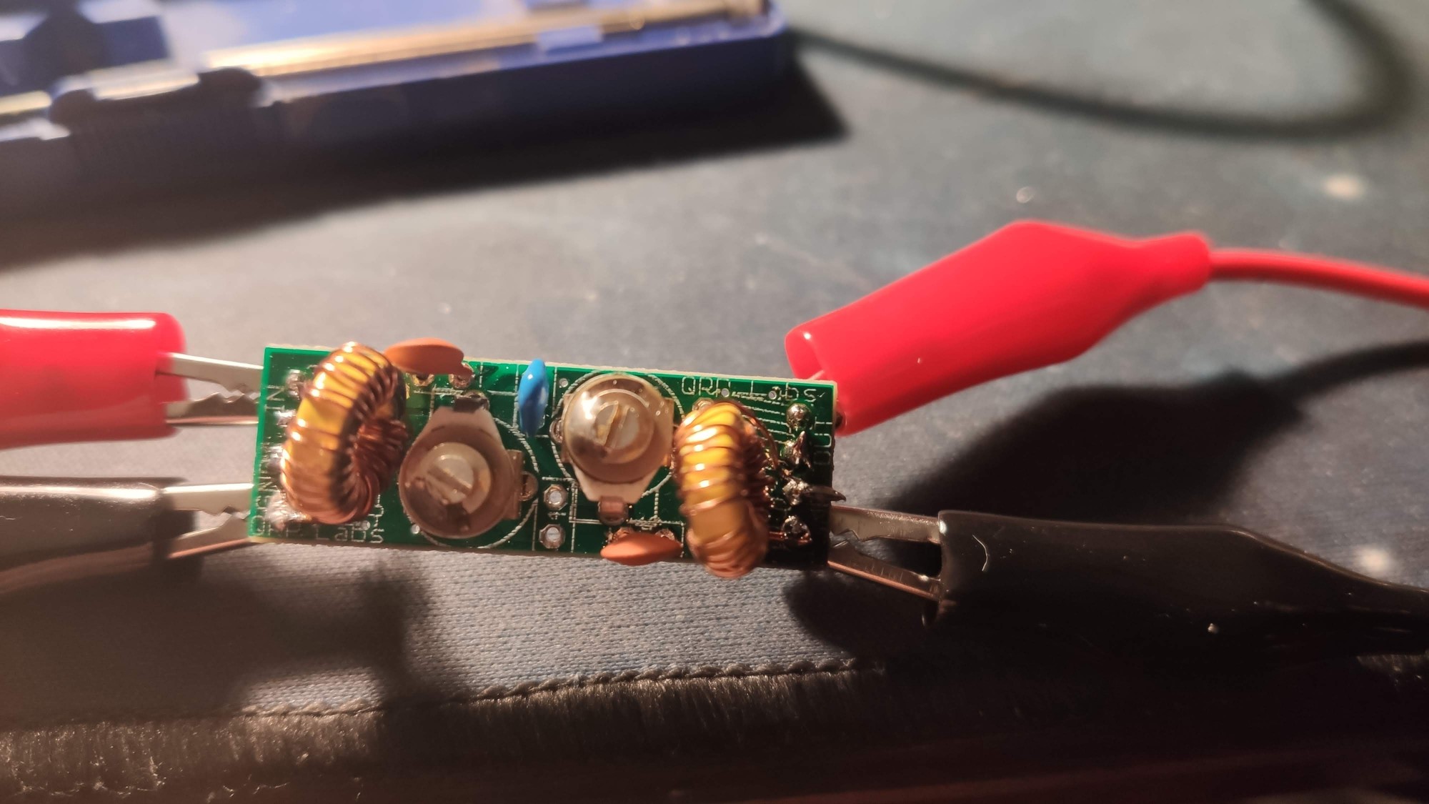
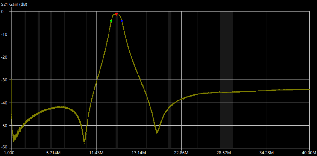
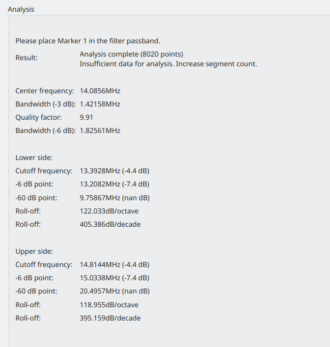
After assembling the filter, I measured its frequency response and compared the results with the QRP Labs specifications. To perform the measurement, I used a NanoVNA connected to my laptop running NanoVNASaver software.
The measured filter shows a bandwidth of approximately 1.42 MHz and an insertion loss of around -1.48 dB, which closely matches the QRP Labs specs of 1.44 MHz bandwidth and -1.75 dB insertion loss.
Si5351A Synthesizer module#
The KEITHSDR board provides 3.3V power on the CN4 connector for I²C devices. The QRP Labs Si5351A synthesizer module can operate at both 3.3V and 5V, and it supports I²C logic levels at both voltages.
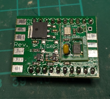
Initially, I built a rev5 synthesizer module, omitting several components as described in the synth-assembly5 guide. This setup worked well, but unfortunately, I accidentally damaged the module. When I acquired a new module, it was the rev6 version (synth-assembly6). Along with this, I also got the TXCO (temperature-compensated crystal oscillator) module, which should provide improved frequency stability over temperature variations. However, I soon discovered that the rev6 board I received appears to be pre-assembled for 5V operation.
To test the new board, I used an Arduino Mega and ran a simple test sketch using the Adafruit_SI5351 library. This code initializes the clock generator and sets up three different outputs using both integer and fractional PLL modes.
Wiring diagram
| Si5351A module | Arduino Mega |
|---|---|
| pin 0 | GND |
| pin 10 | 5V |
| pin 11 | 5V |
| pin 13 | SCL |
| pin 14 | SDA |
  #include <Adafruit_SI5351.h>

Adafruit_SI5351 clockgen = Adafruit_SI5351();

/**************************************************************************/
/*
    Arduino setup function (automatically called at startup)
*/
/**************************************************************************/
void setup(void)
{
  Serial.begin(9600);
  Serial.println("Si5351 Clockgen Test"); Serial.println("");

  /* Initialise the sensor */
  if (clockgen.begin() != ERROR_NONE)
  {
    /* There was a problem detecting the IC ... check your connections */
    Serial.print("Ooops, no Si5351 detected ... Check your wiring or I2C ADDR!");
    while(1);
  }

  Serial.println("OK!");

  /* INTEGER ONLY MODE --> most accurate output */
  /* Setup PLLA to integer only mode @ 900MHz (must be 600..900MHz) */
  /* Set Multisynth 0 to 112.5MHz using integer only mode (div by 4/6/8) */
  /* 25MHz * 36 = 900 MHz, then 900 MHz / 8 = 112.5 MHz */
  Serial.println("Set PLLA to 900MHz");
  clockgen.setupPLLInt(SI5351_PLL_A, 36);
  Serial.println("Set Output #0 to 112.5MHz");
  clockgen.setupMultisynthInt(0, SI5351_PLL_A, SI5351_MULTISYNTH_DIV_8);

  /* FRACTIONAL MODE --> More flexible but introduce clock jitter */
  /* Setup PLLB to fractional mode @616.66667MHz (XTAL * 24 + 2/3) */
  /* Setup Multisynth 1 to 13.55311MHz (PLLB/45.5) */
  clockgen.setupPLL(SI5351_PLL_B, 24, 2, 3);
  Serial.println("Set Output #1 to 13.553115MHz");
  clockgen.setupMultisynth(1, SI5351_PLL_B, 45, 1, 2);

  /* Multisynth 2 is not yet used and won't be enabled, but can be */
  /* Use PLLB @ 616.66667MHz, then divide by 900 -> 685.185 KHz */
  /* then divide by 64 for 10.706 KHz */
  /* configured using either PLL in either integer or fractional mode */

  Serial.println("Set Output #2 to 10.706 KHz");
  clockgen.setupMultisynth(2, SI5351_PLL_B, 900, 0, 1);
  clockgen.setupRdiv(2, SI5351_R_DIV_64);

  /* Enable the clocks */
  clockgen.enableOutputs(true);
}

/**************************************************************************/
/*
    Arduino loop function, called once 'setup' is complete (your own code
    should go here)
*/
/**************************************************************************/
void loop(void)
{
}
This setup confirmed the module was functional and properly communicating over I²C.
By inspecting the Serial Monitor output in the Arduino IDE, we can see that the clock generator is properly configuring all three outputs:
16:34:18.861 -> Set PLLA to 900MHz
16:34:18.861 -> Set Output #0 to 112.5MHz
16:34:18.893 -> Set Output #1 to 13.553115MHz
16:34:18.925 -> Set Output #2 to 10.706 KHz
I then observed the generated signals using an oscilloscope:
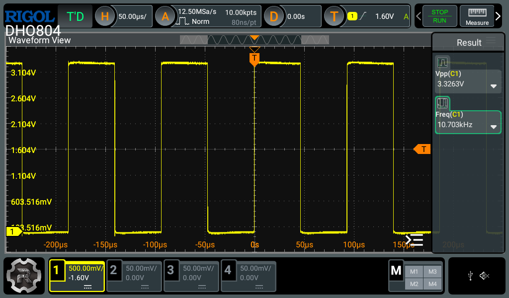
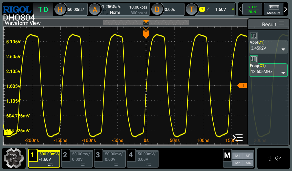
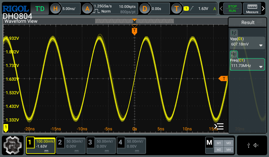
Note: The observed drop in peak-to-peak voltage (Vpp) as frequency increases is due to the oscilloscope’s 70 MHz analog bandwidth. While the DHO804 has a high sampling rate (1.25 GSa/s), signals like 112.5 MHz exceed its analog bandwidth, leading to visible attenuation and reduced Vpp. This is expected and does not reflect a problem with the Si5351A output. 1
QRPLabs Receiver module#
Here is the fully assembled QRP Labs receiver module:
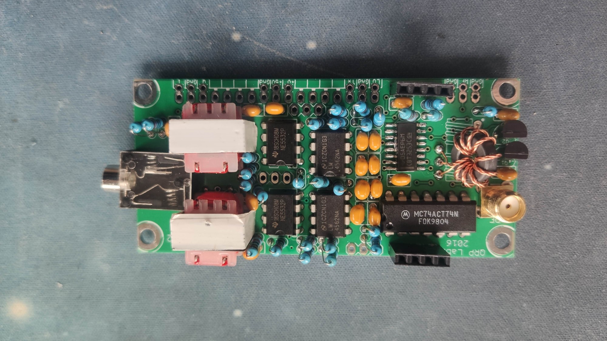
The module’s I/Q output is connected to the Line-In socket on the KEITHSDR main board. This allows the baseband I/Q signals to be captured and processed by the SDR system.
The receiver module is powered by both 12V and 5V, which are supplied directly from the KEITHSDR board. The 12V rail typically powers the analog RF front-end, while 5V is used for digital logic.
Conclusion#
With the QRP Labs receiver, band-pass filter, and Si5351A synthesizer successfully integrated, the reception path of my KEITHSDR build is now up and running. I’ve verified local oscillator operation, measured filter performance, and confirmed I/Q signal output to the SDR board.
In the next post, I’ll cover the audio path and walk through the final assembly of the system. This will bring everything together into a working SDR receiver ready for on-air testing.
-
See the Rigol DHO800 Series datasheet: https://www.rigolna.com/USA-Datasheet/DHO800-Datasheet.pdf ↩︎